
The primary and most effective means of protecting buildings from physical damage is considered to be the Lightning Protection System (hereafter LPS). It consists of both external and internal protection systems.
This article focuses on the construction of the external lightning protection system, specifically the components located on the roof.
To begin with, let’s clarify the purpose of this protection system. According to IEC 62305-3:2012, the external LPS is designed to intercept direct lightning strikes to the structure, including strikes to the façade, and to conduct the lightning current safely from the point of impact down to the ground. It is also intended to disperse this current into the earth without causing thermal or mechanical damage, or dangerous sparking that could lead to fires or explosions.
The likelihood of lightning current penetrating a building is significantly reduced when a properly designed system of air-termination devices is in place. Such a system may consist of any combination of the following components:
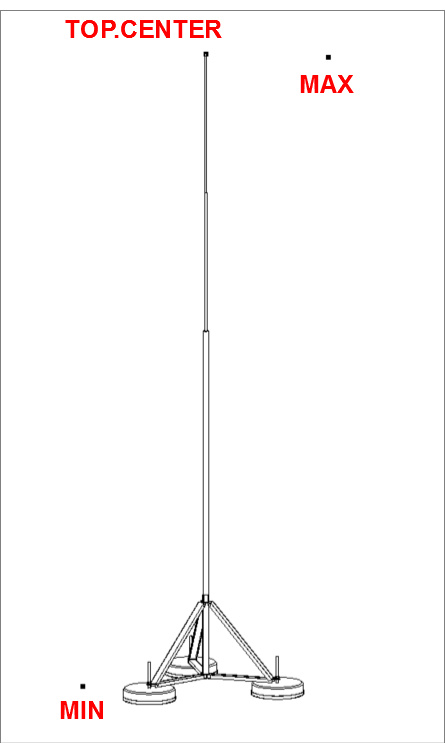
- Rods (including free-standing masts)
- Tensioned wires
- Mesh conductors
The methods used to position the air-termination system include:
- The protective angle method
- The rolling sphere method
- The mesh method
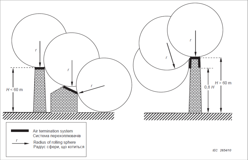
In this article, we will explore the construction of an air-termination system based on the rolling sphere method. This method is applicable in all cases and is considered effective if no part of the building to be protected comes into contact with a sphere of radius R—defined by the LPS class—when the sphere rolls around and over the building from all possible directions. In this way, the sphere should touch only the air-termination devices.
With the theory covered, we can now move on to Revit. To apply the rolling sphere method, we need to prepare the following:
- Air-termination device families (these may have various mounting options)
- An adaptive family to model a portion of the sphere that will make contact with the air-termination devices
- A script that places adaptive points on the tips of the air-termination devices
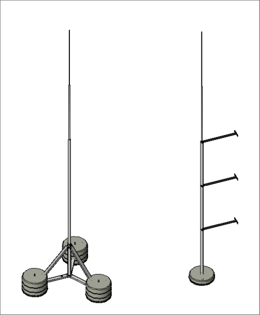
1. Air-termination device families
These can be created from scratch or based on existing families (if available), and placed on the roof to form a lightning interception system for building protection. The placement of air-termination devices is determined by professional judgment and standard recommendations. If any building element or section ends up outside the protected zone, the system’s configuration can always be adjusted accordingly.
2. Adaptive family for a portion of the sphere
To create this component, we use a Conceptual Mass with three adaptive points.
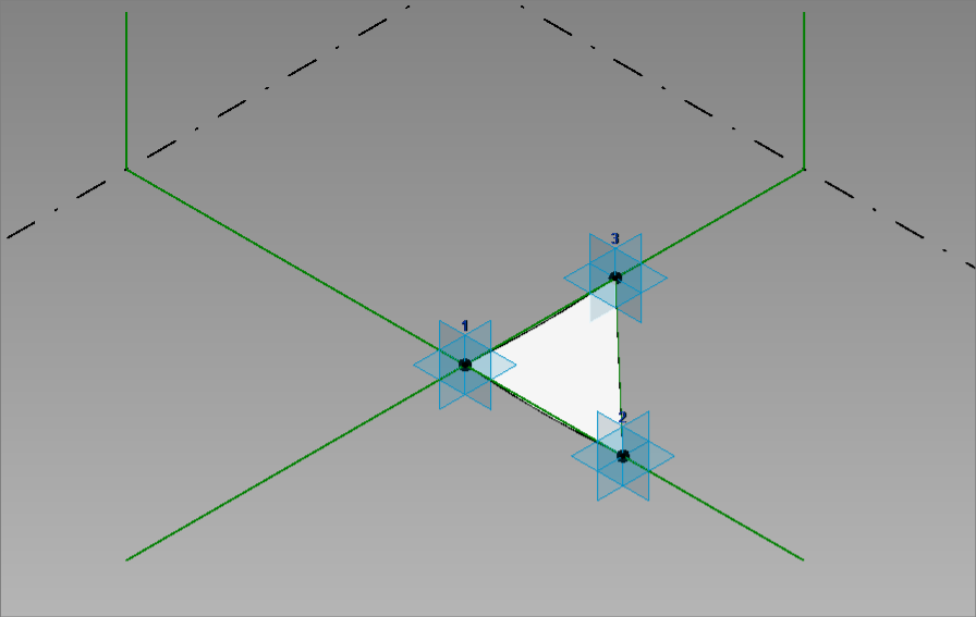
Each of the three points will be placed on the tips of the air-termination devices, simulating the trajectory of the rolling sphere. Why three points? Two points define only a plane (2D), while spatiality (3D) is required for this method. Three points are sufficient to construct a fragment of the sphere, which can then serve as the basis for placing adaptive points on the tops of the lightning rods.
3. Script
The final essential element for implementing the method is a script, which can be roughly divided into three parts. The first part involves identifying all air-termination devices in the project that should be included in constructing the rolling sphere’s trajectory. The second part focuses on determining the central top point among the selected air-termination devices
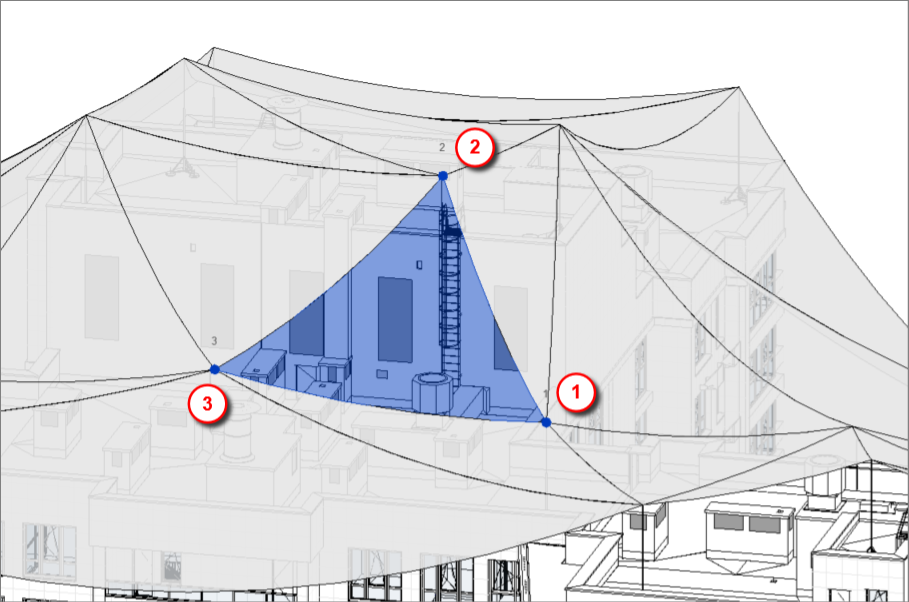
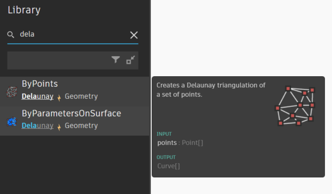
and the third part involves generating triangles based on the collected top points using the Delaunay.ByPoints node.
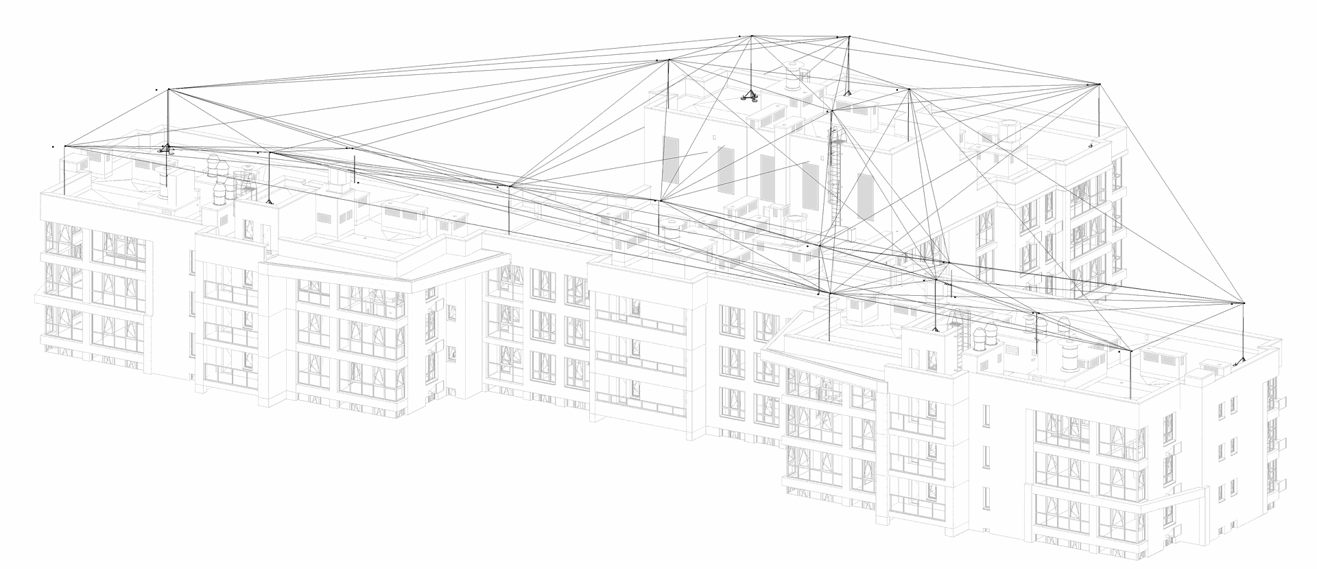
As a result, we obtain all possible combinations of three points. This approach ensures the maximum number of potential rolling sphere trajectories. However, it is not optimal, as a significant number of the generated triangles intersect with each other, making the analysis more complex and negatively affecting the visual clarity of the outcome.
To construct a "clean" triangulation—free of excessive overlaps and with the maximum number of valid triangles—it is advisable to use the external module scipy.spatial.Delaunay from the Python library. This module analyzes all possible combinations of three points, filters out intersecting triangles, and generates the most complete coverage composed of unique, non-overlapping triangles.
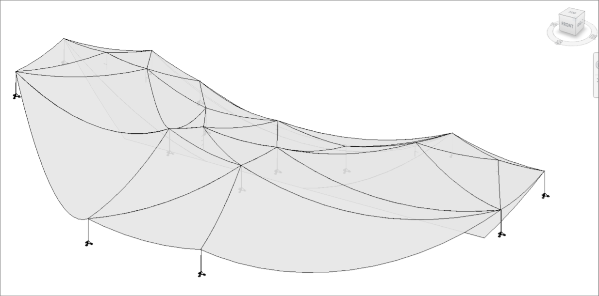
As a result, we obtain the maximum number of possible unique rolling sphere trajectories. This allows for a visual assessment of the effectiveness of the selected air-termination configuration. If any “gaps” in the protection zone are detected, the system can be adjusted accordingly to ensure complete protection of the building against direct lightning strikes.
That`s it.
For those who are just starting to work with electrical systems in Revit or want to organize their foundational knowledge — we recommend the "Autodesk Revit 2025: Electrical Basic" course in Ukrainian, offered by our authorized training center.
The course covers all the key principles needed for a confident start in designing electrical systems in Revit. Upon completion, you will receive a certificate.