Let’s start by defining what a Cable Schedule (CS) actually is.
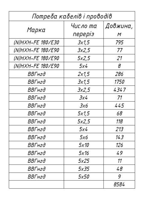
A cable schedule is a systematic list of cable lines that contains information about the power source, load, type, cross-section, and cable length, presented in a tabular format. Using the standard tools available in Revit, we can:
- Obtain data about the power source;
- Obtain data about the loads;
- Perform electrical connections and obtain the lengths of the lines.
Thus, by using the standard tools for working with electrical systems in Revit, we can obtain almost all the necessary data for generating a cable schedule. However, to fully comply with regulatory documentation requirements, two parameters are still missing — the cable type and the cross-section. At this stage, it is most efficient to use a powerful but often underestimated tool — Key Schedules.
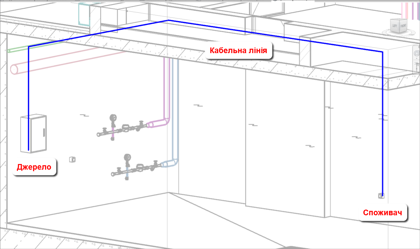
It is best to build the cable schedule within the Electrical Circuits category because it contains data on the power panel, the connected loads, and most importantly, the cable line length.
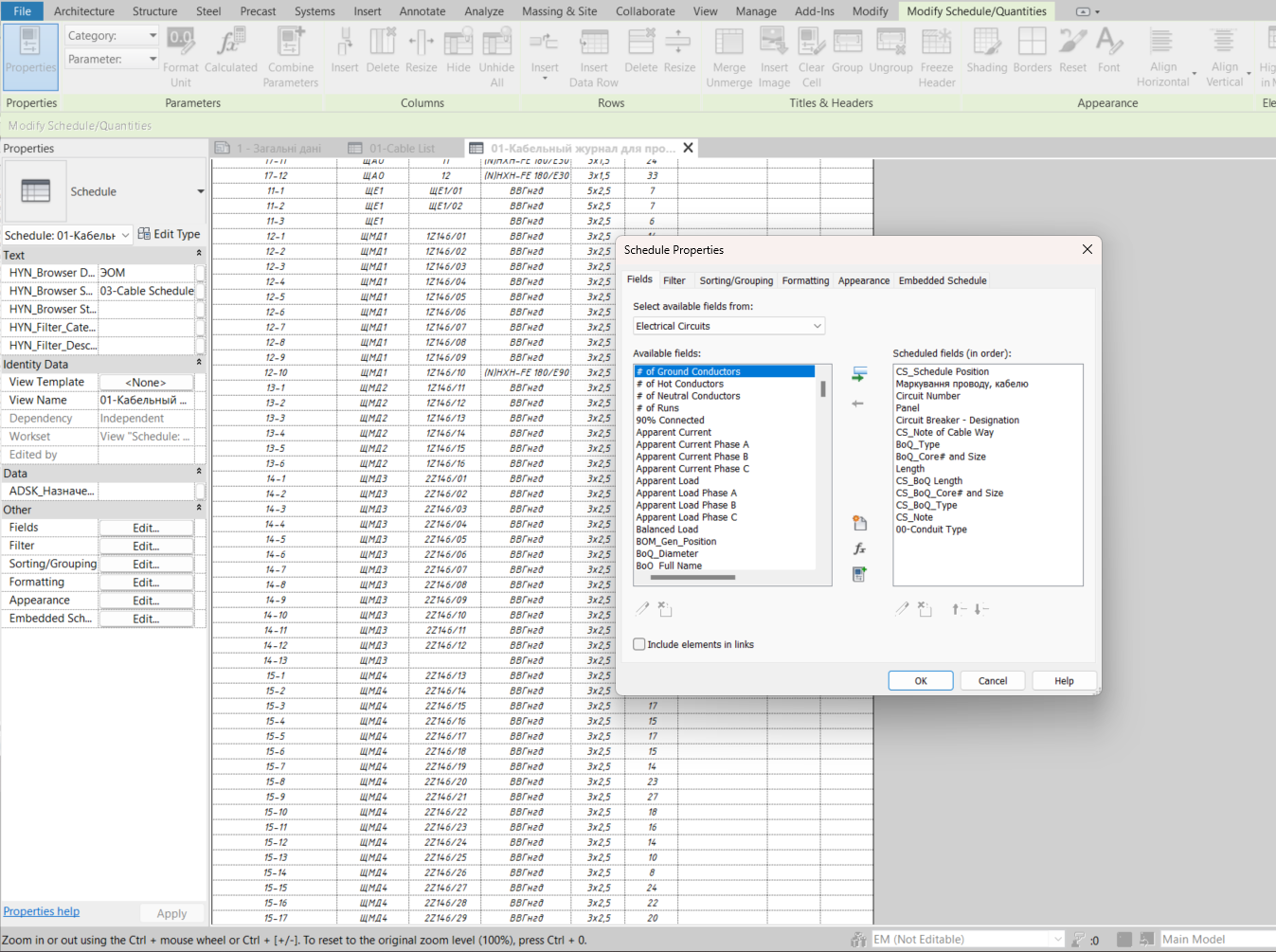
Creating a key schedule for the Electrical Circuits category is no different from creating one for any other category. It’s quite simple: View → Schedules → Electrical Circuits → Key Schedule
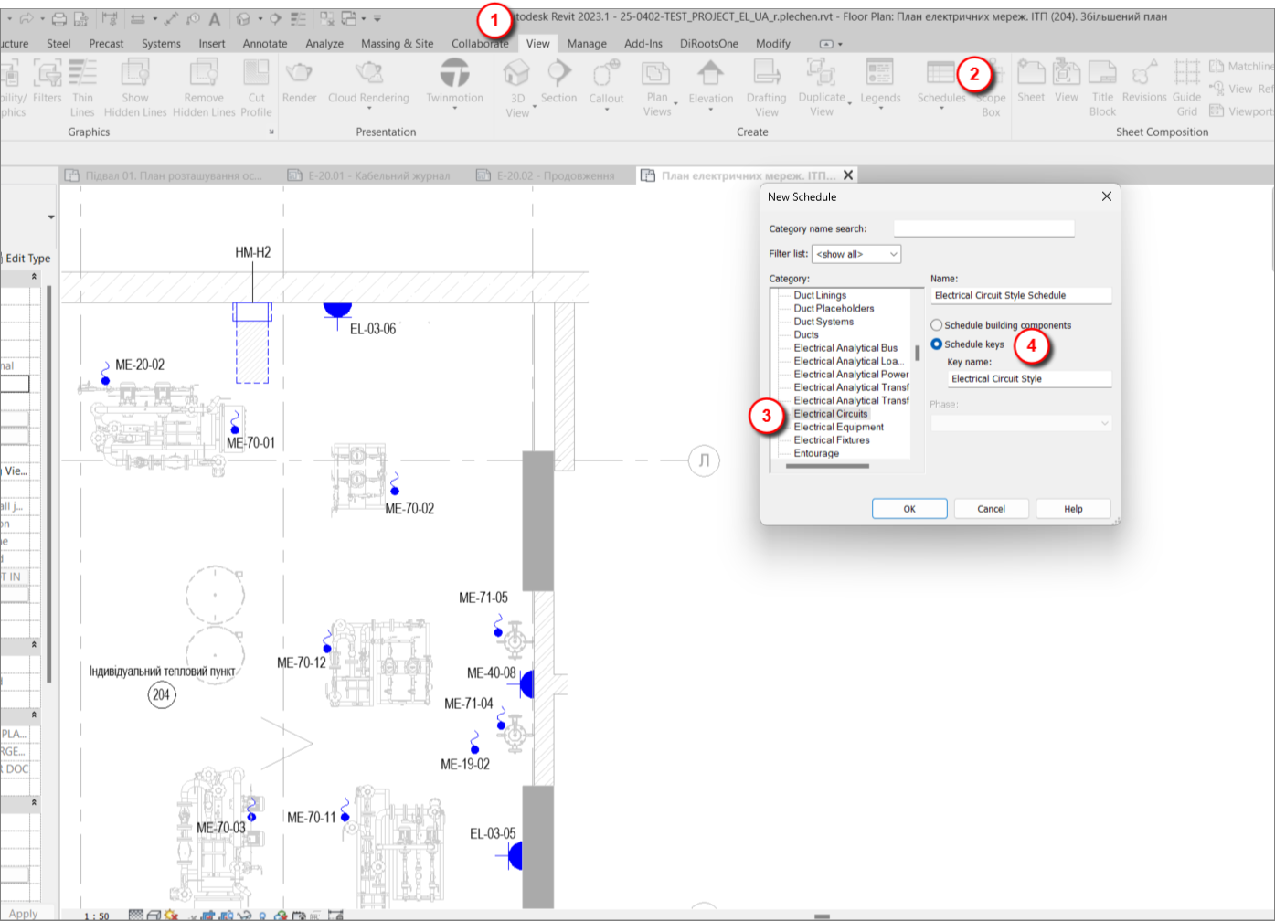
In the opened window, we create parameters that we will fill in manually. By the way, this topic — along with the broader topic of schedules — is covered in our course Autodesk Revit 2025: Electrical Basic.
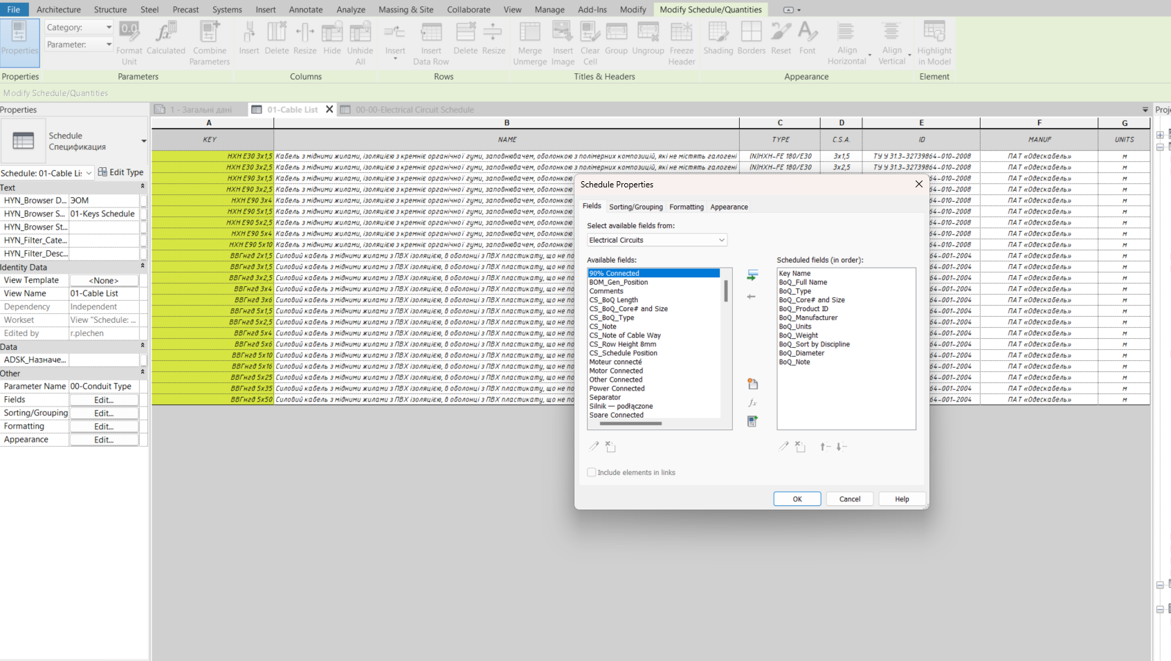
After that, the key schedule for the Electrical Circuits category is ready for use. To apply it, you can either go directly to the circuits and select the needed values for each one individually, or use a faster and more reliable method — create a regular schedule for the Electrical Circuits category and add the appropriate parameters to enable selection. This approach is more reliable since it ensures that nothing is missed, provided the filters are set correctly.
Generally, managing a model using schedules for the relevant categories is much easier and faster. All the necessary instance data is visible at a glance, eliminating the need to search for a specific element to check or modify a parameter — not to mention batch editing parameters for multiple elements located on different levels.
Returning to the newly created Electrical Circuits schedule — for the appropriate parameter, we select the designed cable from the drop-down list. Usually, cable cross-sections are calculated using specialized software or Excel and then manually entered into Revit. However, for users with advanced Revit skills, these calculations can be performed directly within Revit, allowing dynamic tracking of voltage drop and short-circuit current changes when moving instances, and making it possible to adjust the cable cross-section immediately if necessary.
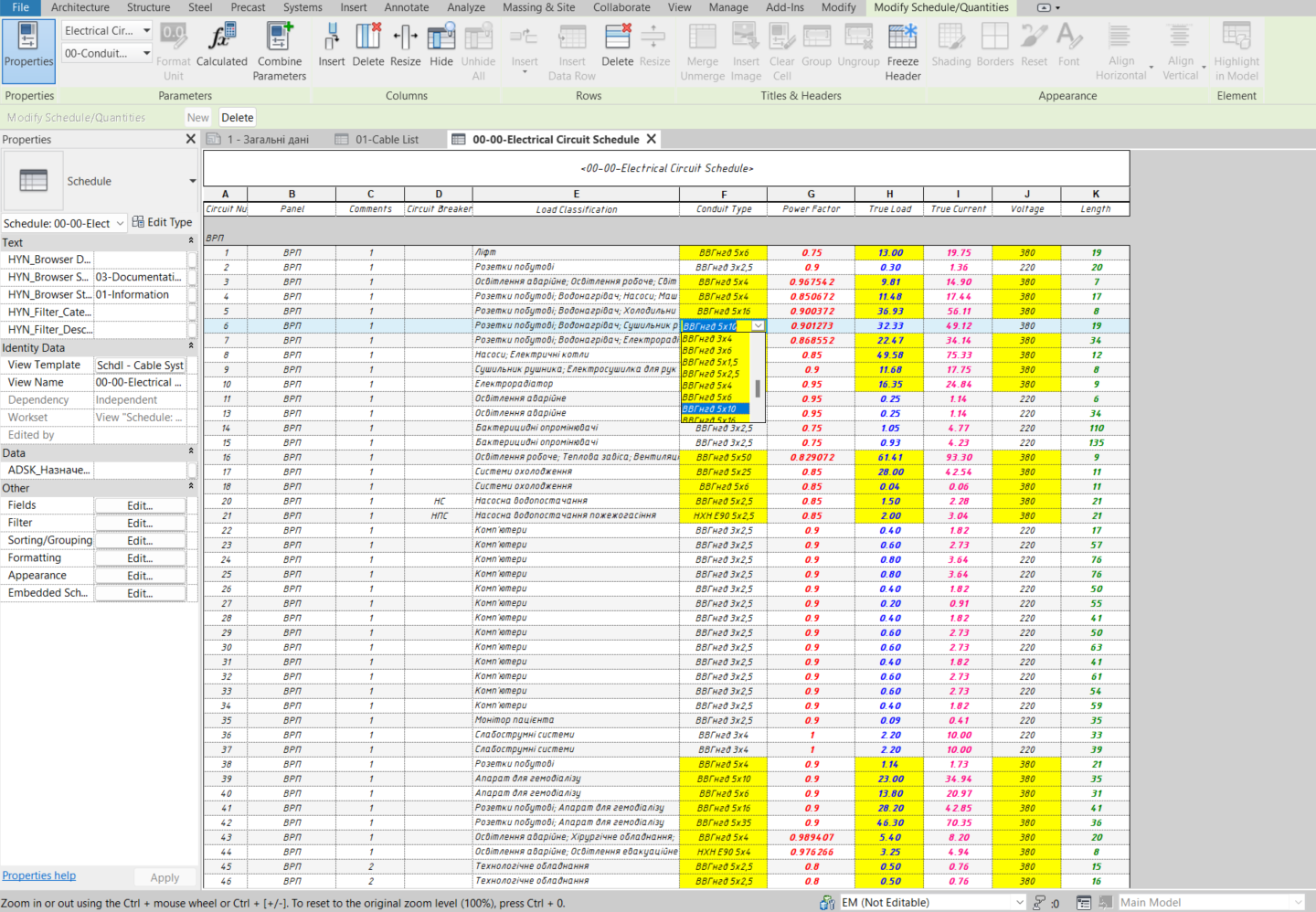
After selecting the required cross-section, we return to the cable schedule and add the newly created parameters to the table.
Now, we have a fully functional cable schedule. If necessary, you can add a cable length reserve using an additional parameter — for example, display the total length as Length + AUX_Length or include the reserve directly in the path length editor.
Thus, we can confidently say that a cable schedule in Revit is not a myth — it’s a reality!